Relative information is summarised from the Online Book of the Practical Electron Microscopy and Database, in the next posts, I will only reference it in the end of the post.
In TEM imaging, the conventional modes of high-resolution imaging are mainly determined by the objective lens defocus. There are four generally used defocus settings:
- “Standard” defocus
- Scherzer defocus maximizing the phase contrast of a weak-phase object
- Lichte defocus of least confusion, minimizing contrast delocalization
- Minimum phase-contrast defocus
Except the first defocus is in-focus, underfocuses are applied to all the other defocus settings because of the existing, positive spherical aberration of the objective lens, which has to be counterbalanced in a certain way by a negative defocus aberration related to underfocus.
The defocus value (Δf) can be determined from the position of the first crossover of contrast transfer function:

Here, n = 0, ±1. That means different integers n give different defoci. For instance, a TEM system has a spherical aberration constant Cs 1.38 mm, is operating at 200 kV (the wavelength is 0.0025 nm), and has the first crossover of Fourier transform at u = 2.75 nm-1. Therefore, three possible defocus values are -15 nm (for n = -1), -70 nm (for n = 0), and 53 nm (for n = 1).
The values of Δf (defocus value), Cs (spherical aberration coefficient), and D (standard deviation of the Gaussian distribution of defocus due to the chromatic aberration) can be obtained by TEM image deconvolution.
Where is defocus from
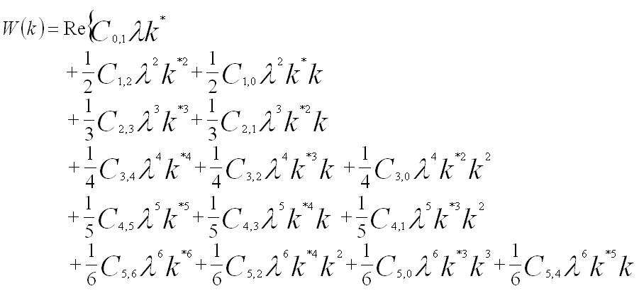
The third- and fifth-order spherical aberration coefficients and defocus are present in a perfect, round electromagnetic lens, while all other higher-order coherent aberration coefficients are caused by lens imperfections.
Under the isoplanatic approximation as well as Taylor expansion, the wave aberration function, W, using the notation provided by Krivanek, can be concisely expanded to sixth order in k about the origin of zero scattering angle in terms of the coherent aberration coefficients, given by,

What is defocus
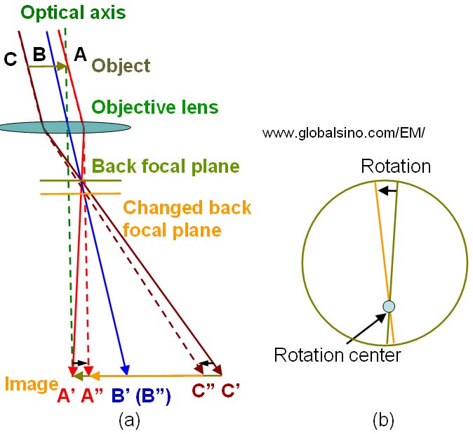
Because of the misalignment of an objective lens, the off-axis electron beam enters the objective lens. And the ABC will form the A”B”C” which will be smaller than the real image A’B’C’ as shown in the figure2, it is because of the change of the back focal plane. And this change will also induce a rotation of the image because of the helical path of the electrons through the lens.
 Fig.1 Misalignment of the objective lens: (a) Sweep of the image, and (b) Combination of sweep and rotation of the image on the viewing screen in the EM.
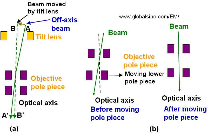
There are two ways to correct this situation:
- Tilting the incident illumination
- adjust the physical positon of the objective lens pole pieces

Next, I will talk about the “Strandard” defocus.
Reference:
-
J.M. Cowley, Electron diffraction phenomena observed with a high resolution STEM instrument, J. Electron. Microsc. Tech. 3 (1986) 25-44.
-
Krivanek, O. L., Dellby, N., and Lupini, A. R. (1999). Towards sub-Å electron beams. Ultramicroscopy 78, 1.
-
Practical Electron Microscopy and Database Online Book: http://www.globalsino.com/EM/